I had hoped that my MIP panels and hardware would have turned up by now especially as I have just had two days off work (to look after my two children as it is half-term week) so although I wouldn’t have gotten away with dedicating my entire couple of days off work to the project I certainly would have had a handful of exciting photo’s to show you as opposed to the random stuff I’ve done the last couple of days.
At the moment the project has stalled really… I am waiting on my panels and hardware to turn up now before any further significant updates can be posted but I was determined to get as much ‘odds and sods’ done these last two days as possible so a breif run down of what I have acheveved the last couple of days:-
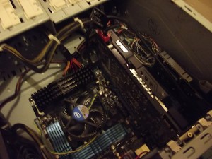
- Installed my second PCI-E GFX card (will be used to power the ECAM displays and MCDU screen)
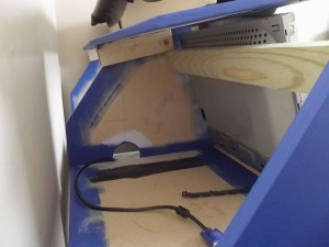
- Additional MIP stand braces and monitor rest.
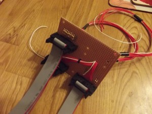
- Started work on the MIP I/O distribution board.

My I7 FS machine with second graphics card just installed into the 3rd PCI-E slot.
The new card that I installed into my FS machine is a ZOTAC nVidia GT210 64bit PCI-E graphics card, yeah… nothing special but as it will only be used to drive the ECAM displays and MCDU display this will do just fine. My external view and PFD/ND displays are running on my nVidia GTX560Ti which is perfect.
I decided to install the GFX card into the 3rd PCI-E slot as opposed to the 2nd slot to hopefully better improve the cooling on my main GTX560Ti card. – Although I’ve installed the GFX card and installed the drivers I have yet to connect it up to a couple of monitor to make sure all is working in harmony… so fingers crossed when I do!
Yesterday morning just needing something to do on the project I decided to add some additional supports to the MIP frame, I added a cross beam to add additional support and also act as a brace to hold the PFD/ND monitor once the MIP panels turn up.

Rear view of MIP stand showing new cross support and glare-shield base mounting battons.
I also cut some smaller battons and attached them to the upper part of the MIP stand to enable more surface area to securely screw down the glare-shield section as there will eventually be rather a lot of over-hanging weight once the FCU and EFIC is properly mounted. -I am just really getting excited to receive my MIP panels as this really will give me a lot more things to work on and will make the project really start moving.
Yesterday afternoon I ordered some components from Spiratronics these included some self-adhesive PCB mounting risers which I will use to securely mount my I/O cards as well as some stripboard and IDC connectors and ribbon cable as I have decided that my new panel hardware will all connect to a single I/O distribution card of which I will in turn be connected to a Leo Bodnar BBI-32 card and a USBOutputs card.

The MIP I/O distribution card.
This is how it currently looks, As you can see I have made up a few ribbon cables which will be used to connect to the back of the MIP Auto-brake and Audio panels which will then connect the inputs and outputs (buttons, switches, encoders and LED’s) to the MIP I/O distribution board which will be mounted in the lower ECAM part of the MIP stand and it’s main function to keep all the wiring tidy as soon the MIP stand will no doubt become a maze of various cables for the displays, korry switches, console lighting etc.
I still need to wire up the upper IDC socket to some equipment wire which will be crimped with some boot lace crimps and then will be routed to behind the main board and then connected to one of my USBOutput cards. The photo on the left currently only shows the inputs wired which still need to then be soldered to a BBI-32 card but this is how far I have got so far.
I will post more photo’s once I have finished all the wiring on this card and mounted it in the MIP stand – it will become more apparent as to how and why I have decided to build this card to better help with cable management etc.
Bed time now – back to work for me tomorrow!


