Category Archives: Computer Systems

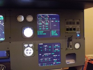
MIP panels mounted, Auto-brake and Loudspeaker panel testing.

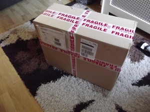
The delivery of the MIP, auto-brake, loudspeaker and landing gear lever has arrived!

This weekend I took delivery of my first order of panels and hardware, I spent saturday mounting the panels and making a few alterations to the MIP frame to ensure the ECAM monitor fitted correctly. I soon realised that the 19inch wide-screen is actually too narrow and actually longer than required so I will eventually switch this out for a standard 19inch monitor which should then mean I can make use of both of the upper left standby instrument windows.

Testing flight for the new panel’s and electronics.

After a whole day of soldering the Korry switches in the auto-brake and loudspeaker panel I managed to give them a ‘test-flight’ from Belfast (EGAA) to London Stansted (EGSS) with a greased landing rate of -131fpm 🙂 – I took various photo’s of the panels and korry LED’s in action which can be seen on the photo gallery page.

I’ve also posted a quick ‘test’ video on YouTube showing the panels and korry switches in action 🙂 – The video can be found here: http://youtu.be/Kh2Ri2Xju2w.

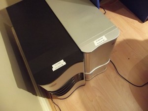
The two PC setup running the flight simulator and flight deck.

I’ve now properly configured my second PC for off-loading some of the tasks of the main FSX PC (FS-MASTER) onto a new PC (FS-CTRL1) which now runs WideFS, ActiveSky, pmSounds SIOC (all USBOutput cards are connected to this PC). Now that the Auto-brake panel and Loudspeaker panel I also tested connecting the BBI-32 card to the remote PC and to my surprise I am extremely pleased to report that you can have BBI-32 and BU0836X cards connected to a remote PC using WideFS and it still registers button presses etc on the main FSX PC… which is awesome meaning that I will now connect both you input cards and output cards to the second PC all communication with the main FSX PC is then done over WideFS. Meaning that now the only thing my main FSX PC (FS-MASTER) does is run FSX, run the four displays (external view, PFD/ND, ECAM and standby instruments) and will have the side-stick, pedels and throttle levers leaving the other tasks (Weather Engine (ActiveSky 2012), ATC (FSInn), Flight deck sounds (pmSounds), Running the USBOutput cards (SIOC) and have all the BBI-32 cards to run the MIP panel switches and the OHP switches and rotaty encoders).

More updates soon! 🙂
 

Working on the sound and vibration systems in the cockpit

Well I had really hoped that this weekend I would have received the MIP panels but unfortunately they still haven’t arrived as yet…

Yesterday evening I also added a new page to my site outlining how the cockpit sounds and vibration systems are going to be done, the software and hardware involved as well as some tweaks (as the Wilco Airbus does not fully separate the panel sounds from the spoiler, flaps and gear ‘drag’ noises.) more details can now be found on the ‘Sounds and Vibration systems‘ page.

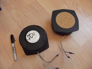
The two bass shakers (tactile transducers) that I bought on eBay last week have arrived!

Despite not feeling well at all today I made the most the day and since my tactile transducers arrived earlier in the week I was determined to get some ‘rumble’ in my cockpit

So I cut and screwed down some old chipboard to the seat box of where I have now mounted the two 25watt tactile transducers, I took apart an old Logitech 2.1 speaker system in the hope that the built in amplifier would power the two tactile transducers.

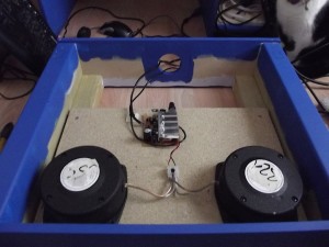
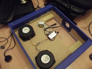
Original set-up, mounted underneath the seat the Tactile transducers are powered from the amp PCB that I salvaged from the old Logitech 2.1 sound system and 12v ATX power supply.

Originally when I dismantled the Logitech speaker system I left the transformer inside as I caught a glimpse that the output voltage was 12 volts of which I thought ‘great – I’ll connect the amplifier PCB up to my external ATX power suppliers which will be providing power to other parts of the cockpit’ of which I did do in the first place (photo on the left shows the original setup making use of the 12 volt DC power from my ATX power supply)

Once I did a quick flight test, I noticed that the bass and centre speaker from my Creative Inspire 5.1 sound system (or which is connected to the main FSX machine to a ‘splitter’ with the separate amplifier that was running the tactile transducers) started to get some feedback so I soon figured that there was something wrong… Double checking the transformer I found that it was in fact 12v AC so I dismounted the captains seat from the lower box and changed the wiring back so that the AC transformer was driving the amplifier PCB this then worked fantastic and stopped causing feedback that I had previously experienced.

Second attempt… Transformer fitted!

So, I decided to then connect my iPhone up to the 2.5mm splitter (to test the sound through both the tactile transducers and centre/bass speaker) it was awesome!!! – I played a couple of songs while sitting in the captains seat and the vibration was awesome and that was without any EQ tuning too I was extremely happy with the results until…. I decided to check the temperature of the heat sink/transformer   that was running the tactile transformers, both where extremely hot so I’ve now disconnected it until I can get my hands on a 100 watt+ dedicated amplifier as I figure the small amplifier PCB is just isn’t up to the job unfortunately.

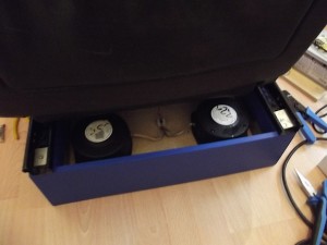
Bass shakers (Tactile transducers) mounted in the seat box.

Despite the issues with needing to obtain a powerful amplifier I’m happy that the two tactile transducer are mounted and are giving good results so as soon as I have sorted the dedicated 100+ watt power amplifier the captain’s seat will be all sorted 🙂 – I’ll been keeping my eye out on eBay for some more tactile transducers as ideally I’d like to have one running inside the pedestal (to generate vibration so when holding the thrust levers it feels realistic on take-off etc.) and maybe one in the MIP structure/side-stick pedestal just to give more realistic vibration to the controls of which I will be in contact with so it really does feel like I’m flying an aircraft with some beefy engines behind me.

I really hope that tomorrow I’ll feel much, much better and if that is the case I will certainly re-build my old Intel Core2 Duo machine with Windows 7 64bit and prepare it as the sounds, WX, USBOuputs and comm’s (ATC) machine.. This machine will be running WideFS, pmSounds, SIOC, ActiveSky 2012, BlueSky (ACARS tracking software that I use ) and FSInn.

Adding the leather trim to the centre pedestal and new FSX build

I’ve been rather busy recently so have not done much else on the cockpit but to be honest even if I hadn’t have been busy I wouldn’t have been able to do all that much anyway as the weather in England has been pretty drab the last four weeks meaning that I wouldn’t have been able to get out in the garden to cut and work on the remaining bits of my centre pedestal and a few other bits and peices.

Earlier this week however I did a clean FSX build on my main flight simulator PC as I wanted to incorporate all my latest software and ensure that both of my graphics cards are installed and configured as part of the build. Well it took a couple of days of solid work to install a fresh copy of Windows 7 Professional (64bit), configure FSX, tweak it and install all my various scenery add-ons etc. I have literally just finished taking a full system image of both of my HDD’s using Acronis TrueImage 2012 (my main machine is running 1x 500GB 7200RPM mechanical HDD for Windows and a single 128GB SSD for FSX and all my add-ons) .

I’ve also been very interested in looking into merging the Wilco Airbus with the Project Airbus model for various reasons… firstly is that most people know that the Wilco external model is rather rubbish when compared with the Project Airbus model, another really cool feature of the Project Airbus model is the Wing flex! – I successfully merged my Wilco with the Project Airbus model and have now included this as part of the build and is the aircraft I will be flying in my flight sim!

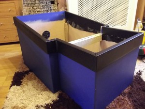
Centre pedestal with leather trim

So this afternoon, it was surprisingly nice and sunny (despite being still rather chilly outside) so I decided to make the most of it and as I’ve borrowed my mums upholstery stapler I thought I’d add the leather trim and edging to the centre pedestal the results of which look pretty good in my opinion 🙂

So first of all I started off by cutting some 6mm MDF that I had left over and was surplus to requirements, the 6mm MDF was actually a perfect width for what I needed and now that the pedestal leather trim has been added looks great!

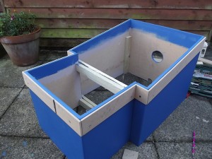
The 6mm MDF rim

So taking measurements from the Simpit.de website, I found that the height of the pedestal rim was 7cm, so I cut a 7cm rim for the entire pedestal and then using 1.0 inch wood screws initally screwed them into the pedestal as a ‘dry run’ as shown in the photo on the left.

Showing the faux leather stapled to the pedestal and then the wooden rim screwed back in over the top.

I figured that to make a decent job of it I need to securly attach the leather to the pedestal and then wrap it around the pedestal rim and then strech and staple down on the inside of the pedestal.

I have not yet added the internal panel rails as yet but this will be the final bit to do to the pedestal but so far I am extremely happy with the results. I’ll aim to add the panel mounting rails in a few weeks time but obviously that is dependent on weather and my next order that will be arriving is for my MIP so I’ll be working hard on that before I need to do anything else on the centre pedestal.

Folding and stapling down the faux leather… starting to take shape!

It was rather tricky to then pull the leather back up and over the 6mm MDF but luckily the leather is stretchy and once I had worked the corners a bit it folded over nicely and I managed to staple it down and it started to really look good (in my opinion anyway).

More photo’s of today can be found over at my Photo’s section.

Some more good news…. apparently I should be recieving my first order (being the MIP panels and hardware) this week so I should then have some more photos and blog updates very soon! – I can’t wait to get the MIP panels all fastened to the MIP frame and the hardware connected to my I/O.

Stay tuned… more updates very soon 🙂