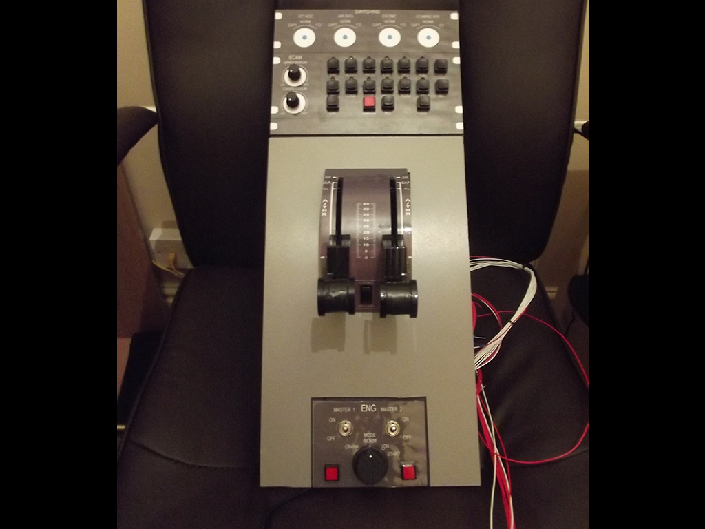
At the start of this project I decided that probably the very last bit I’d do would be to purchase a good quality replica throttle quadrant as they are pretty much one of the most expensive parts to purchase for a home cockpit project, at about £1500.00 it certainly is a large purchase and I therefore decided that for now at-least I would use my existing Saitek Throttle Quadrant, make a few alterations to the internals, design and customise the leavers with some Airbus like throttle handles.
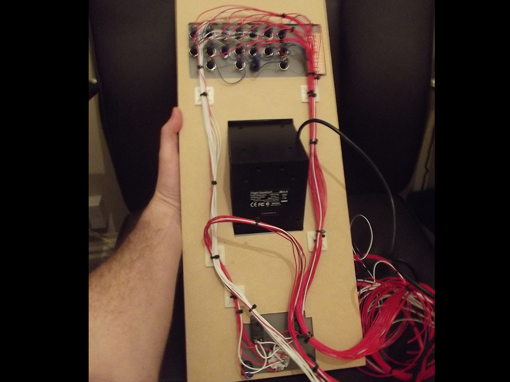
 I’ve posed details and photo’s of my Saitek throttle quadrant modification on a separate page… The TQ is mounted to this panel through a rectangular cut space and then sits nicely in the centre of the panel assembly, as most throttle quadrants also come with the engine starter panel integrated I have added this to the panel too and I’ve also implemented the ECAM switching panel at the top. This single panel now fits nicely into my pedestal and although is mounted to a single 3mm MDF sheet is designed to look like three separate panels.
I first started off by getting the panel measurements to ensure they are to scale and so that it fitted into my pedestal and then cut out a peice of 3mm MDF sheet of which I used to strengthen the PVC panels and mount them on.
I then looked for photo’s online to get an idea of the ECAM switch and Engine Starter panel proportions. Using Adobe Illustrator I then designed the panels, printed them, laminated them and then cut out the required holes for the mounting of the switches and rotary encoders etc.
The ECAM switch panel also incorporates 12x 3mm green LED’s of which will be driven by one of my USBOutputs cards. – It was no fun having to cut those little holes out though 😉
Once I had cut out the switch mounting holes from the Engine Starter panel and ECAM switching panel I then proceeded on to marking the holes onto the 3mm grey PVC foamex, using a HSS drill peice I then drilled the holes for the LED’s, Switches and encoders.
Now that the panel was ready to be assembled, I used double-sided sticky tape to stick down the sides and corners which was sufficient as once the switchgear was mounted, they held the laminated panel design in place which is great. Once everything was mounted and locking nuts tightened it was time to begin the soldering of all the components…
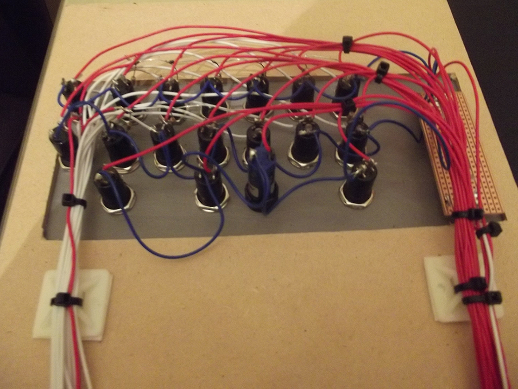
I started off by soldering resistors inline to the LED’s on the positive leg and connecting 0.2mm wires to the legs, the OpenCockpit USBOutputs card uses a ‘positive’ common so and as you can see from the photo on the right hand side of this page – the white coloured wires (on the left of the photograph) are the 5v negative connections of which I then crimped with 1.0mm bootlace connectors which works great with the USBOutputs card connectors.
Once the LED’s where tested on my modified ATX power supply using a 5v feed I then started to solder the momentary switches and soldered the two ECAM brightness encoders to a small piece of stipboard and then wired that in to the main ‘inputs’ loom which was then all cable-tied together and then secured to the back of the 3mm MDF using some cable tie mounts that I purchased the other week from B&Q.
Once I was happy with all the soldering I then glued (with super glue) the 3mm PVC panels to the back of the 3mm MDF to give it extra straight especially as the centre of the panel will be holding the throttle quadrant and likely to be under stress during flight with me resting my hand on the TQ etc.
So there you have it… this will be my Airbus’s throttle quadrant, ECAM switching panel and Engine Starter panel until such time as I have obtained the other replica panels that are higher on my priority list of which will then eventually be replaced by a professionally built, motor driven replica throttle quadrant, engine starter panel and ECAM switching panel and more than likely be the last piece of hardware that is replaced.

