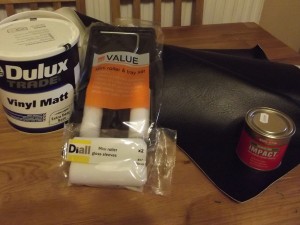
During the week the faux leather turned up which I mentioned about ordering in my previous blog post and for £14 from eBay I was well impressed… I now have a 200cm (2m) by 131cm (1.3m) cut of fire resistant faux leather of which I will be using to cover my glare shield with, top-part of my side-stick pedestal and of-course the rim around the top of the centre pedestal… hopefully it will do the job and make the cockpit look great!
On my lunch break at work yesterday I took a trip across town to B&Q and purchased a small roller set for a couple of pounds, two extra foam roller head’s (I plan on using one for each coat in case they go funny after each coat – when they dry out etc.), some Evostick IMPACT glue which I will use to stick the faux leather to the MDF and of-course the specially mixed Airbus structural paint colour (RAL5017 in a Matt Emulsion finish) – In total the bits that I purchased from B&Q yesterday cost me £32 which I cannot really complain at 🙂
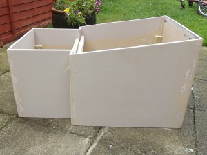
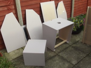
After applying the first coat of primer (Spare emulsion that I had in the shed) to my MDF panels and the pedestal last weekend, I was keen to wake up early this morning and get out in the garden to sand down the panels ready for their second coat of primer.
I was lucky with the weather and all day it remained generally sunny so I was able to fully apply the second coats of primer to all the panels including pedestals sections and then they all dried happily in the sun allowing me to the start on the seat box of which I would mount my BMW seat on top of…
So having found some 2×4 timber in the shed and doing some research online (watching a few YouTube video’s of Airbus cockpits) I soon came to the decision that using one length on its side and one laying down raised the seat adequately – The seat I am using has some fancy controls on the side also allowing me to lower or raise the seat within a range of about 100mm (10cm) which is also pretty cool so I have some room at-least of errors 😉
So once I was happy with the general height of the seat – I worked this out mainly by comparing my seating position (my knee location against the upper pedestal compared to that of the first officers in this YouTube video) I then attached the seat runners to the wood with two large woodscrews and two pieces of cut out aluminium plate that I used as a washer for the rear holes as the woodscrew’s head passed through the rear holes.
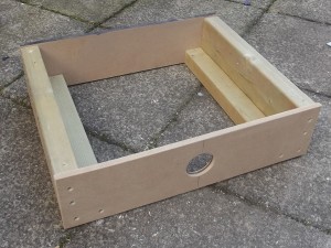
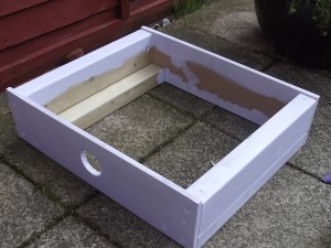
Once mounted, the seat was very stable and I then screwed the lower piece of 4×2 on its flat side to the upper piece of 4×2 which the seat was mounted to, to strengthen up the two runners I then used some 12mm MDF cut to size (140mm high by 540mm wide) and then screwed across the two new raiser blocks to create a box like structure.
As you can see from the image, I also used a hole cutting drill piece to drill a hole in the front of the seat box in case I later wanted to install some foot well lighting or had a need to feed some cables through.
Now that the seat-box/stand was ready to be primed I found another tin of surplus emulsion from the shed (as I had used up the other tin on the panels and pedestals earlier today) and then primed that too and is now drying in the garden as we speak (well as I type this blog entry!)… Once its dry I’ll pop out and just pop some wood filler in the counter sunk wood screws so that hopefully tomorrow when I get back on with the project I’ll be able to sand it down and have a full smooth surface ready for the second coat of primer.
So as its getting on now and I’m due to head off out this evening I’ll be calling it a night until tomorrow morning, where and when hopefully it will be nice weather again all day and I can then get on with the bits and pieces that I hope to achieve tomorrow which are:-
- Sand down and apply second primer layer to the seat-box/stand.
- Lightly sand down all the panels and the pedestal and apply the first coat of RAL 5017 (…exciting!)
- Start work on the side-stick pedestal.
Fingers crossed the weather will be as good tomorrow 🙂
Hi Bobby
I am just setting out on building an A320 cockpit. The one thing I am struggling to find is the dimensions for the support structure that sites behind the main instrument panel (as per your parts drying, above). If possible could you send me dimensions? I am a network systems engineer by trade and totally useless with woodworking so any measurements etc would be really helpful! I will look forward to the day my build looks like yours!
Kind regards
Richard