Category Archives: Electronics

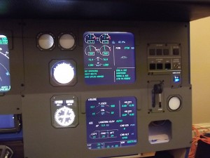
MIP panels mounted, Auto-brake and Loudspeaker panel testing.

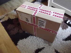
The delivery of the MIP, auto-brake, loudspeaker and landing gear lever has arrived!

This weekend I took delivery of my first order of panels and hardware, I spent saturday mounting the panels and making a few alterations to the MIP frame to ensure the ECAM monitor fitted correctly. I soon realised that the 19inch wide-screen is actually too narrow and actually longer than required so I will eventually switch this out for a standard 19inch monitor which should then mean I can make use of both of the upper left standby instrument windows.

Testing flight for the new panel’s and electronics.

After a whole day of soldering the Korry switches in the auto-brake and loudspeaker panel I managed to give them a ‘test-flight’ from Belfast (EGAA) to London Stansted (EGSS) with a greased landing rate of -131fpm 🙂 – I took various photo’s of the panels and korry LED’s in action which can be seen on the photo gallery page.

I’ve also posted a quick ‘test’ video on YouTube showing the panels and korry switches in action 🙂 – The video can be found here: http://youtu.be/Kh2Ri2Xju2w.

The two PC setup running the flight simulator and flight deck.

I’ve now properly configured my second PC for off-loading some of the tasks of the main FSX PC (FS-MASTER) onto a new PC (FS-CTRL1) which now runs WideFS, ActiveSky, pmSounds SIOC (all USBOutput cards are connected to this PC). Now that the Auto-brake panel and Loudspeaker panel I also tested connecting the BBI-32 card to the remote PC and to my surprise I am extremely pleased to report that you can have BBI-32 and BU0836X cards connected to a remote PC using WideFS and it still registers button presses etc on the main FSX PC… which is awesome meaning that I will now connect both you input cards and output cards to the second PC all communication with the main FSX PC is then done over WideFS. Meaning that now the only thing my main FSX PC (FS-MASTER) does is run FSX, run the four displays (external view, PFD/ND, ECAM and standby instruments) and will have the side-stick, pedels and throttle levers leaving the other tasks (Weather Engine (ActiveSky 2012), ATC (FSInn), Flight deck sounds (pmSounds), Running the USBOutput cards (SIOC) and have all the BBI-32 cards to run the MIP panel switches and the OHP switches and rotaty encoders).

More updates soon! 🙂


Working on the sound and vibration systems in the cockpit

Well I had really hoped that this weekend I would have received the MIP panels but unfortunately they still haven’t arrived as yet…

Yesterday evening I also added a new page to my site outlining how the cockpit sounds and vibration systems are going to be done, the software and hardware involved as well as some tweaks (as the Wilco Airbus does not fully separate the panel sounds from the spoiler, flaps and gear ‘drag’ noises.) more details can now be found on the ‘Sounds and Vibration systems‘ page.

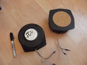
The two bass shakers (tactile transducers) that I bought on eBay last week have arrived!

Despite not feeling well at all today I made the most the day and since my tactile transducers arrived earlier in the week I was determined to get some ‘rumble’ in my cockpit

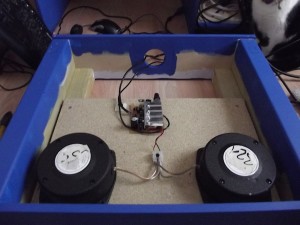
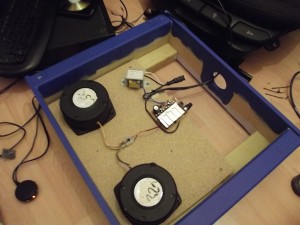
So I cut and screwed down some old chipboard to the seat box of where I have now mounted the two 25watt tactile transducers, I took apart an old Logitech 2.1 speaker system in the hope that the built in amplifier would power the two tactile transducers.

Original set-up, mounted underneath the seat the Tactile transducers are powered from the amp PCB that I salvaged from the old Logitech 2.1 sound system and 12v ATX power supply.

Originally when I dismantled the Logitech speaker system I left the transformer inside as I caught a glimpse that the output voltage was 12 volts of which I thought ‘great – I’ll connect the amplifier PCB up to my external ATX power suppliers which will be providing power to other parts of the cockpit’ of which I did do in the first place (photo on the left shows the original setup making use of the 12 volt DC power from my ATX power supply)

Once I did a quick flight test, I noticed that the bass and centre speaker from my Creative Inspire 5.1 sound system (or which is connected to the main FSX machine to a ‘splitter’ with the separate amplifier that was running the tactile transducers) started to get some feedback so I soon figured that there was something wrong… Double checking the transformer I found that it was in fact 12v AC so I dismounted the captains seat from the lower box and changed the wiring back so that the AC transformer was driving the amplifier PCB this then worked fantastic and stopped causing feedback that I had previously experienced.

Second attempt… Transformer fitted!

So, I decided to then connect my iPhone up to the 2.5mm splitter (to test the sound through both the tactile transducers and centre/bass speaker) it was awesome!!! – I played a couple of songs while sitting in the captains seat and the vibration was awesome and that was without any EQ tuning too I was extremely happy with the results until…. I decided to check the temperature of the heat sink/transformer   that was running the tactile transformers, both where extremely hot so I’ve now disconnected it until I can get my hands on a 100 watt+ dedicated amplifier as I figure the small amplifier PCB is just isn’t up to the job unfortunately.

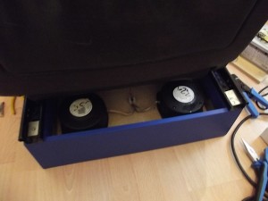
Bass shakers (Tactile transducers) mounted in the seat box.

Despite the issues with needing to obtain a powerful amplifier I’m happy that the two tactile transducer are mounted and are giving good results so as soon as I have sorted the dedicated 100+ watt power amplifier the captain’s seat will be all sorted 🙂 – I’ll been keeping my eye out on eBay for some more tactile transducers as ideally I’d like to have one running inside the pedestal (to generate vibration so when holding the thrust levers it feels realistic on take-off etc.) and maybe one in the MIP structure/side-stick pedestal just to give more realistic vibration to the controls of which I will be in contact with so it really does feel like I’m flying an aircraft with some beefy engines behind me.

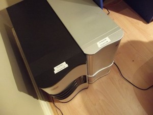
I really hope that tomorrow I’ll feel much, much better and if that is the case I will certainly re-build my old Intel Core2 Duo machine with Windows 7 64bit and prepare it as the sounds, WX, USBOuputs and comm’s (ATC) machine.. This machine will be running WideFS, pmSounds, SIOC, ActiveSky 2012, BlueSky (ACARS tracking software that I use ) and FSInn.

MIP I/O board complete!

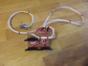
The completed MIP I/O distribution board

Following on from my last blog post when I started working on my MIP I/O distribution board, after a couple of days at Legoland with Nikki and the children I got home last night and decided that this morning I would complete the MIP I/O board.

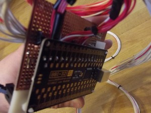
So the MIP I/O card now has the Leo Bodnar BBI-32 card soldered to the inputs and mounted on the reverse of the MIP I/O distribution board, as a temporary measure I’ve used some self adhesive PCB mounts.

Back of the MIP I/O board.. wires soldered on to the reverse of the BBI-32.

While I was away on Friday the USB Socket B order turned up which enabled me to solder the socket on to the dedicated Leo Bodnar BBI-32 card which worked great.

So today I had to solder all the output wires to the board and the other end of the wires I crimped with bootlace crimps the same way that I did for my temporary ECAM switch panel as these crimps work great with the OpenCockpits USBOutputs card.

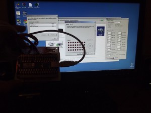
MIP I/O distribution card connected to my PC and me testing and configuring the encoders inputs.

Once all was ready I connected the BBI32 up to my flight simulator PC and ran the BBI-32 configuration software to configure inputs 1 – 2 and 3 – 4 as encoders, the remaining 9 inputs will be used as standard switches so no further configuration was needed.

The BBI-32 card that is now attached to the back of the MIP I/O card is dedicated to the MIP I/O board – I don’t intend on using the other unused 19 inputs as I ideally want to keep this I/O card fully dedicated to the MIP.

I have another 2 BBI-32 cards of which I will be using for my overhead panel once I am ready to start that.

I hope everyone that went to FSWeekend had a great time, I would have absolutely love to have gone but we had already pre-booked a trip to Legoland in Windsor (London), maybe next year for me! 🙂

Installed my seconds GFX card, additional braces added to the MIP stand and MIP I/O distribution board started.

I had hoped that my MIP panels and hardware would have turned up by now especially as I have just had two days off work (to look after my two children as it is half-term week) so although I wouldn’t have gotten away with dedicating my entire couple of days off work to the project I certainly would have had a handful of exciting photo’s to show you as opposed to the random stuff I’ve done the last couple of days.

At the moment the project has stalled really… I am waiting on my panels and hardware to turn up now before any further significant updates can be posted but I was determined to get as much ‘odds and sods’ done these last two days as possible so a breif run down of what I have acheveved the last couple of days:-

  • Installed my second PCI-E GFX card (will be used to power the ECAM displays and MCDU screen)
  • Additional MIP stand braces and monitor rest.
  • Started work on the MIP I/O distribution board.

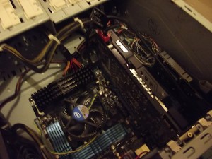
My I7 FS machine with second graphics card just installed into the 3rd PCI-E slot.

The new card that I installed into my FS machine is a ZOTAC nVidia GT210 64bit PCI-E graphics card, yeah… nothing special but as it will only be used to drive the ECAM displays and MCDU display this will do just fine. My external view and PFD/ND displays are running on my nVidia GTX560Ti which is perfect.

I decided to install the GFX card into the 3rd PCI-E slot as opposed to the 2nd slot to hopefully better improve the cooling on my main GTX560Ti card. – Although I’ve installed the GFX card and installed the drivers I have yet to connect it up to a couple of monitor to make sure all is working in harmony… so fingers crossed when I do!
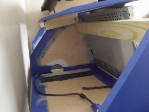
Yesterday morning just needing something to do on the project I decided to add some additional supports to the MIP frame, I added a cross beam to add additional support and also act as a brace to hold the PFD/ND monitor once the MIP panels turn up.

Rear view of MIP stand showing new cross support and glare-shield base mounting battons.

I also cut some smaller battons and attached them to the upper part of the MIP stand to enable more surface area to securely screw down the glare-shield section as there will eventually be rather a lot of over-hanging weight once the FCU and EFIC is properly mounted. -I am just really getting excited to receive my MIP panels as this really will give me a lot more things to work on and will make the project really start moving.
Yesterday afternoon I ordered some components from Spiratronics these included some self-adhesive PCB mounting risers which I will use to securely mount my I/O cards as well as some stripboard and IDC connectors and ribbon cable as I have decided that my new panel hardware will all connect to a single I/O distribution card of which I will in turn be connected to a Leo Bodnar BBI-32 card and a USBOutputs card.

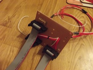
The MIP I/O distribution card.

This is how it currently looks, As you can see I have made up a few ribbon cables which will be used to connect to the back of the MIP Auto-brake and Audio panels which will then connect the inputs and outputs (buttons, switches, encoders and LED’s) to the MIP I/O distribution board which will be mounted in the lower ECAM part of the MIP stand and it’s main function to keep all the wiring tidy as soon the MIP stand will no doubt become a maze of various cables for the displays, korry switches, console lighting etc.
I still need to wire up the upper IDC socket to some equipment wire which will be crimped with some boot lace crimps and then will be routed to behind the main board and then connected to one of my USBOutput cards. The photo on the left currently only shows the inputs wired which still need to then be soldered to a BBI-32 card but this is how far I have got so far.
I will post more photo’s once I have finished all the wiring on this card and mounted it in the MIP stand – it will become more apparent as to how and why I have decided to build this card to better help with cable management etc.
Bed time now – back to work for me tomorrow!

Video demo of USBOutputs and my upper pedestal LED’s

Yesterday I decided to hook up my two OpenCockpit’s USBOutputs cards and test out my SIOC script.

Although I had all intentions of adding a full SIOC tutorial including how to install the software, configure the card device ID’s and import my SIOC script my desktop recording software decided that it didn’t want to work so instead I decided that I’d upload a quick demo of the USBOutputs card working with my SIOC script.

I apologise first and foremost for the many ‘umms’ and ‘uahh’ noises in the video – I hate recording my self and got nervous during the video so I am sorry – I hope that in my next video I can just relax a little and hopefully will be a better video!

Watch the video here: USBOutputs demonstation with the Wilco Airbus Evolution series.

Hopefully I will be able to get my desktop recording software sorted over the weekend and I will record a full tutorial for those that are building a Wilco Airbus home cockpit that wish to use my SIOC script.

MIP built, some nice trim added to the glare-shield and LCD screens ready!

Only spent a few hours on the cockpit today but things are moving along nicely, today I mainly relocated the painted MIP frame into my spare bedroom of where the cockpit will mainly be developed over winter as next year I’ll be looking to build a dedicated brick building for it in the garden.

So today to quickly summarise before I go into detail and post up some photo’s these are the main things that I achieved today:-

  • Constructed the MIP stand in the spare bedroom.
  • Mounted the seat on the newly constructed and painted seat stand.
  • Covered my glare-shield cover in faux leather.
  • Dismantled some monitors ready for the MIP panels.

I have been having withdrawal symptoms from not flying online recently so I did a couple of flights today (EGSS -EGAA) but afterwards I cleared out my spare room (what was my home-office) bought in the panels from the shed and using some newly acquired dry lining screws (black in colour) I then screwed the MIP frame together –  this is the first time since painting the panels that I have screwed it all together and I was really impressed with how it looked and one the MIP screen panels are mounted will look just fantastic! 🙂
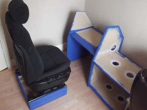
The MIP frame constructed and seat fully mounted.

Next I went up into the loft and found the upper part of what is now my captain’s seat and then screwed and mounted the seat to the painted seat stand… things are now coming together nicely  – I have not yet re-located the centre pedestal from the shed into the house as yet as I’ll need the space when installing the new MIP panels, LCD screens, I/O hardware and electronics  for the MIP panels once they arrive – I’m hoping that the MIP panels, landing gear level and the other MIP panel’s will turn up this coming week so I can sort out the entire MIP next weekend as I’m now at a stage where I have done as much as I can until I get some more of my bits that I have ordered.

As I knew I was planning on covering the glare-sheild this weekend, I gave my mum a call during the week in the hope that she would have an upholstery stapler (a heavy duty staple gun) as being an artist she generally works with canvas and wooden frames and was happy to find that she did so that saved me spending yet more money and I was lucky enough to be able to borrow it…. So today came the time to cover the glare sheild sections in the faux leather to make it look like how the real aircraft does and I was extremely happy with the results.
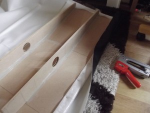
Applying the Faux Leather over a layer of foam sheet to give a slight cushion effect to the glare-shield.

Since I first started building my Mk.1 cockpit I had been saving some sheet foam type of cloth which I finally managed to use by layering underneath the top glare-shield cover to give a padded feeling, see the photo on the right of how I achieved this by first stapling the foam layer and then applying the leather over the top… the end result is extremely authentic!
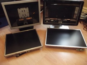
LCD screens removed and now bezel-less and ready for mounting into the MIP section.

Now that I had run out of staples and was unable to start the upper padded pedestal rim (that should be covered with faux leather too) I decided to take appart a couple of LCD monitors which I will be using inside my MIP frame (1x 17inch LCD monitor and 1x 19inch widescreen) I was surprised just how easy it was to remove the bezels and outer monitor housing – I’m now just waiting for the MIP monitor panels to arrieve so I can then ensure that when I mount the LCD screen’s they are in the required positions.

Plans for tomorrow then… I should probably spend the morning with the children (my two girls, Molly and Ruby) maybe take them to the park for a couple of hours if the weather is nice as I’ve neglected them a little the last couple of weekends! – Tomorrow afternoon though I’ll more than likely do another flight and then wire up my custom upper centre pedestal panel to a BBI-32 card and the USBOutputs card and do a video explaining how I utilise the USBOutputs card the BBI-32 as I know a friend of mine (Joerg) is interested in how the USBOutputs card works with the Wilco, so I’ll be demonstrating that 🙂
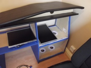
My achievement today.. Two bezel-less screens, MIP constructed and the glare-shield covered with faux leather!

So at the end of today this is what the MIP and glare-shield looks like – be aware that this is not where the actual MIP will be placed, this is just a temporary place so I can work on it over winter before moving to a larger room/building that I have planned for the back garden.

More updates tomorrow evening hopefully! – Thanks for reading! 🙂
Very productive weekend… Priming, sanding and ECAM/Throttle/Engine panel

I had a very active weekend on my project this weekend, here is a quick summary of what I achieved this weekend:-

  • Primed my pedestal (that I constructed last weekend).
  • Primed my MIP frame and glare-shield casing.
  • Screwed and glued the glareshield housing together.
  • Confirmed that B&Q will mix RAL codes.
  • Designed and printed the upper centre panels for my pedestal (ECAM brightness, ECAM mode switches and LED indicators as well as Engine starter panel), mounted and soldered in all the electronics.

So a little more in-depth now then…

From my last post that I made about last weekend, I found some old emulsion paint (a creamy colour that I had previously used to decorate a room in my house) of which was surplus to requirements and perfect for priming my MDF pedestal, the reason for priming the MDF is two reasons really firstly to seal the MDF, as you may know MDF is terrible for absorbing moisture and after cutting and sanding my panels the MDF fibres are left very exposed by coating the MDF in emulsion you are sealing the MDF and will be less prone to swelling due to moisture etc. in the future the other reason is to provide a good surface to paint the final layer(s) on later 🙂

I also had a nice surprise yesterday when I came across my MIP stand components which I had previously cut out last year (I had completely forgotten I had done that :)) so on Saturday I gave my pedestal a good coat ensuring the outer/visible walls and all cut  edges had a good coat of emulsion, I left to dry overnight and then lightly sanded down with sandpaper to remove the brush strokes etc and generally give a smooth even feel and then applied a second coat and is now back in the shed… ready for next weekend along with my MIP frame of which I also primed!

The next step once all items have been primed, sanded, a second primer layer applied and sanded once more will then be to apply several layers of the final colour, as mentioned above B&Q have confirmed they can mix colours based on a RAL colour code which I am extremely happy to hear 🙂 – Weather permitting I’ll make a trip to B&Q this weekend to get the colour mixed for the pedestal and MIP frame – I have heard that prices for custom paint mix starts at £22.

Sorry to be working backward but on Saturday I concentrated on getting my upper pedestal panel complete (well started and complete) as I am using a customised Saitek Throttle I needed to incorporate that into a panel, currently the cheapest Airbus Throttle and Engine Starter panel is over £1,500 (well out of my price range when I have many more important things to sort out for now) so I decided to incorporate the ECAM panel, throttle and engine starter panel on a single panel but made to look as if it was three (photos to come). All the momentary switches, toggle switches, encoders and rotary switches are now mounted and spent many hours yesterday soldering LED’s, resistors and switches together…. all of which seem to be working OK but still need to do the final test if FSX later on.

The upper centre pedestal panels was designed by myself in Adobe Illustrator (a great vector design tool) and then printed off, laminated then then carefully cut out with a Stanley knife (I should probably use a Scalpel knife but I didn’t have one to hand) the holes for the switches and LED’s etc then marked the 3mm PVC foamex before drilling the holes…. the Foam-ex is semi ridged and gives the switches a sturdy   mounting plate. After that was ready and confirmed that the PVC holes lined up with the laminated panel holes I then used double sided tape to stick the laminated panel design to the PVC panel and then finally mounted all the switches and LED’s and the Saitek Custom Throttle.

All-in-all a VERY productive weekend… lets see what next weekend brings although on my ‘to-do’ list of which I hope to achieve is as follows:-

  • Get the side-stick stand out of the loft, get that finished – a whole needs cutting for my Logitech Attack3, sanded down, primed… ideally want to elevate the left side of the stick and provide a slanted look stick (using some precision cut and sanded MDF)
  • Apply the second coat of primer to the MIP frame panels.
  • Give a final sand to the pedestal now that it has had both of it’s primer layers applied.
  • Get some PVC Faux leather cloth ordered from eBay (during the week hopefully to have in time for the weekend)
  • Get the Airbus blue colour mixed by B&Q.
  • All going well and I do manage to get the Airbus blue paint from B&Q, I will then apply a total of three layers using a foam roller to the Pedestal and MIP stand… After leaving for a week to dry etc I will then aim to upholster the glare-shield top and pedestal rim using the Faux leather to complete the pedestal and glare-shield 🙂

Really good progress (in my opinion) so far, still loads more to do but I am looking forward to it and gives me stuff to do 🙂